Martin's Personal Telephone Exchange Museum
 Page created March 2000
, Updates March 2010.
Page created March 2000
, Updates March 2010.
A quick glimpse at some of the telephone switching equipment I have
preserved
I have tried to gather some pictures to give a flavour of the equipment
I
have saved, but it is not always possible to get ideal shots of
equipment which has
exceeded the space available for it! I hope this quick tour will
nevertheless convey
some idea of the work involved and, for those who have never seen
inside an exchange,
reveal the nature of an electromechanical telephone exchange.
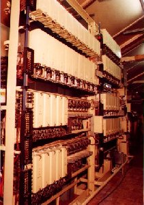
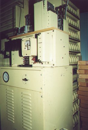
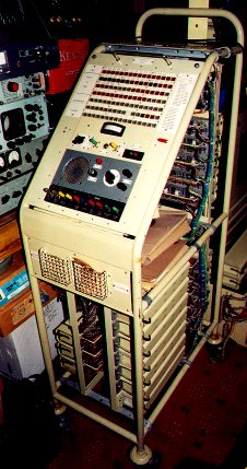
The rural exchange depicted here, is known as a type UAX13. This was
my first real big rescue operation back in 1991. These exchanges were
designed
to be built in Unit contstruction, hence the term Unit Automatic
Exchange. Originally
designed before the second world war, they served the rural communities
of the
UK until 1996, when the last ones were closed at Elvanfoot
and Crawfordjohn in Scotland.
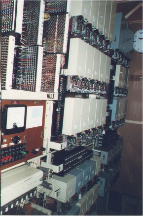
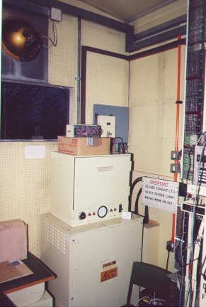
This picture shows my first small hut in which I had preserved only 3
racks, enough to provide pre-STD service
to 100 subscribers.
Click on any of the following pictures to see a larger version,
then use your browser's Back button
to return to this page.
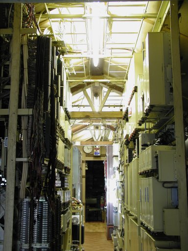
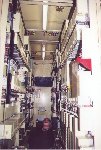
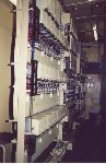
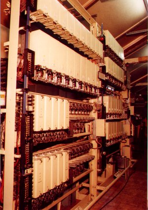
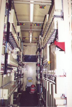
Here is the new apparatus room layout following a major reorganisation
in 2010. At last I have all 9 racks of the U13 in one place as they
should be. In addition to the first 2 A racks and the C rack on the
left, there are
2 F racks, 2 B racks and G and H racks. F and G racks were added
later when Subscriber Trunk
Dialling was introduced
after 1959. The G rack contains the Coin & Fee Checking relay sets
used with
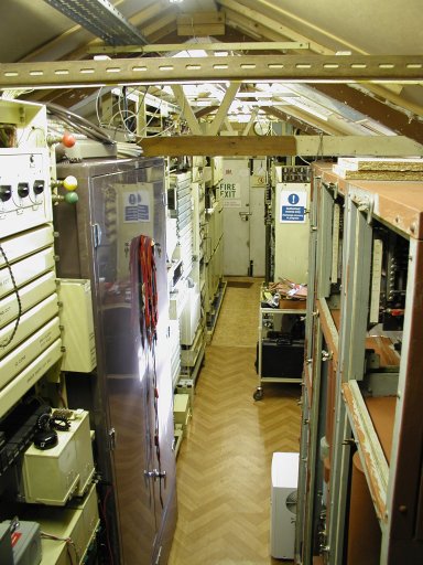
Pay On Answer coin collecting boxes. On the right is a view
looking the other way around. In the foreground on the right are the 3
UAX12 racks rescued from Glenprosen in 2009, still undergoing
restoration.On
the left can be seen the PABX1 and a PABX4 ringer rack. In the far
distance are the U13 B, F and G racks. The U13, known as "Lashford",
can be
accessed from CNET on the
STD code 086741.
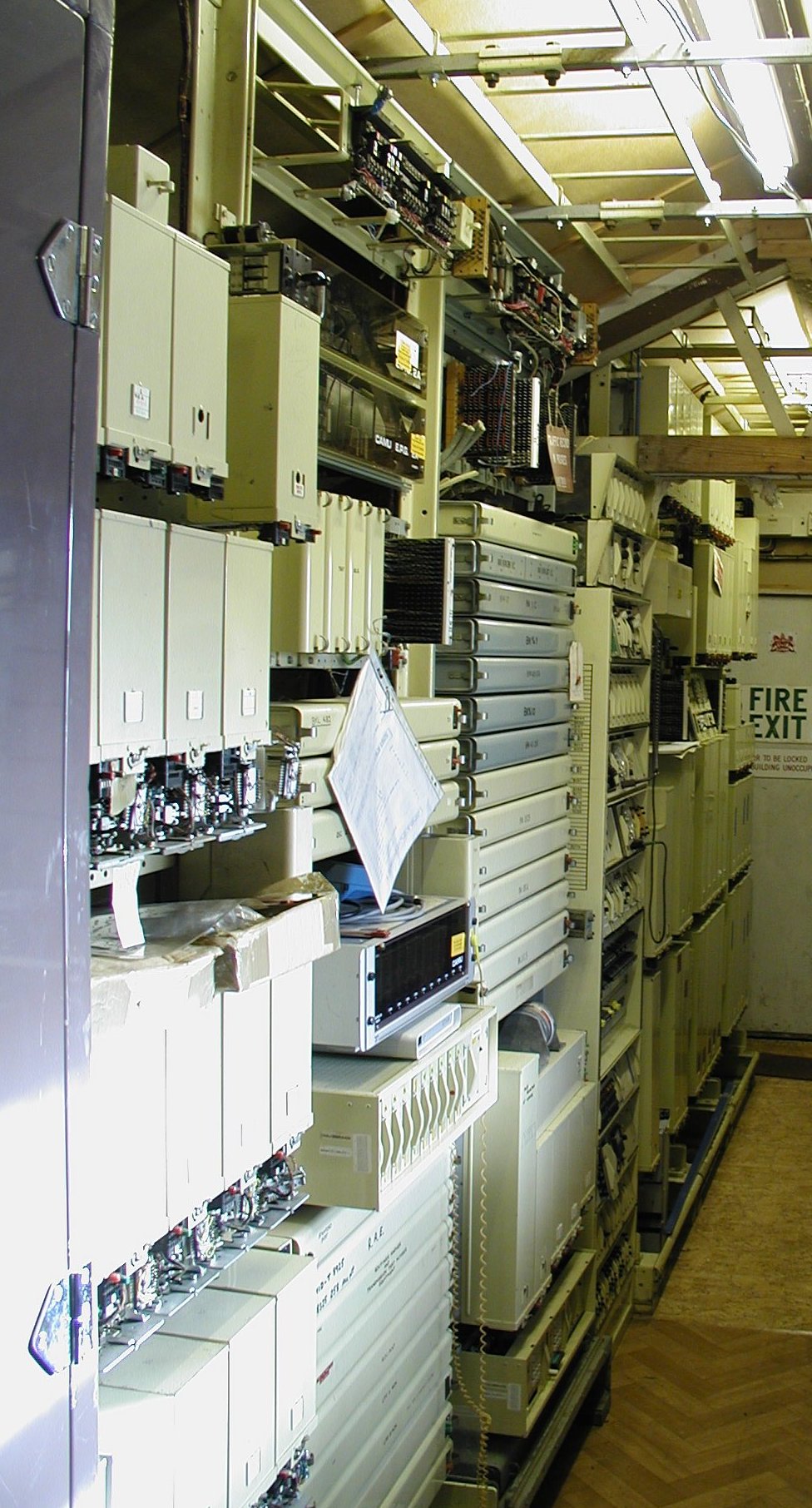
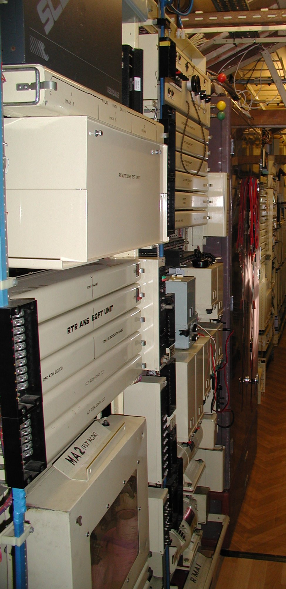
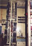
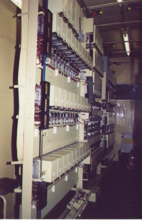
Here are more U13 racks, including a B rack containing some relatively
modern
apparatus. At the top are
two EPG2A electronic pulse generators for local call timing. In the
centre is a CAMU
electronic device for inserting 5 meter pulses for calls to Directory
Enquiries. This was added
when charging for such calls was introduced for the first time, and was
an example of how electronics
became 'bolted on' to Strowger, in order to cope with modern
developments which are otherwise trivial
to add to digital switches. There are also various other relay sets
provided to handle automatic
calls from testing routiners.
In between the second B rack and the U13 F racks is an audio rack type
62.
PABX3 racks from Crawley Hospital,
recovered 1994. The near rack is a
Line & Final Rack, and the far rack is a Group selector rack. There
is
equipment here to form a 100 line PABX. There were 4 L&F racks, two
Group racks and 2 RSR racks in the
Crawley exchange. Unfortunately my colleague, who also saved some
racks, needed the Ringer rack. However,
I have enough ringer shelf equipment to construct a ringer shelf on a
spare Group rack shelf.
There is also one cord board switch section from the 3 originally
at Crawley.
This exchange has now been passed on to another enthusiast as I no
longer have space available.
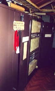
These are two PABX1 systems. One is 7+35 and the other is 10+49. I feel
I don't need two so I parted with the smaller version some years ago. I
kept the one that was recovered from a demolition site
and needed rack straightening before
I could do any other repairs. Before being crushed, it was as new and
refurbished with hardly any use. There
it was in the rubble, complete with diagrams. The other was recovered
in nice condition from Banbury, where
a notice next to it declared it to be the last PABX1 ever fitted in the
Banbury area.
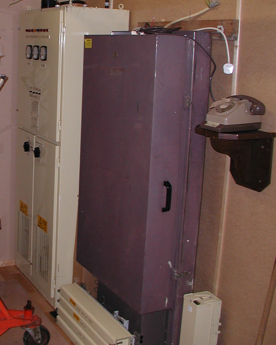
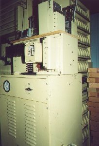
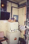
On the left is a 20+5 system known as PABX5. And beyond that a 50 volt
power plant.
On the right is the replacement for the PABX5, the PABX6.
Unfortunately this system was scrapped as no one would give it a home,
and it had been quite badly vandalised in the derelict building before
I saved it.
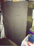
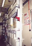
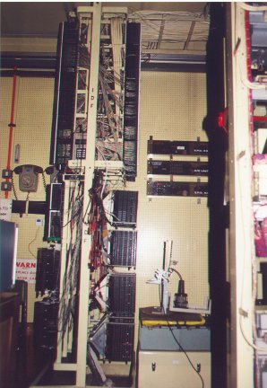
Some more odd racks on the left. There is a routiner docket printer and
a ringer rack. On the right is the power plant which charges the 50
volt cells which
power all the equipment.
Just behind can be seen the 62 type transmission rack equipment.
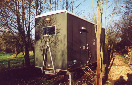
This is my mobile Non-Director exchange. Known as MNDX 341, it was made
in 1971 and was a batch of 200
ordered by the GPO for use as standby exchanges for emergency use. It
is a complete 400 line exchange
built to the same design and standards of a main exchange, except that
it uses shorter racks and is mounted
into a four wheel trailer. Weighing 7 tons, it was only intended to be
wheeled short distances into
position on site, having been transported on the road by low loader.
MNDX 341 was one of about 20 held
in the South Eastern region. They were more often used as temporary
means to expand exchanges where
capacity was running out, as was the case at
"West Forest" Mobile exchange at Wokingham.
Use in real emergency situations was rare. Some of the interior
fittings had unfortunately been removed
before I was able to rescue the MNDX, but I have endeavoured to restore
it to near original state,
as some of the pictures below will show. Access is possible from CNET on STD code 086742.
Click on any of these images to see an enlarged version,
and use your browser's Back button to return to this page.
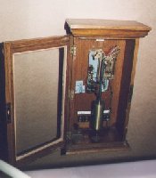
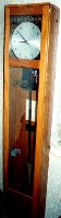
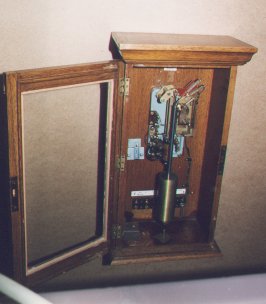
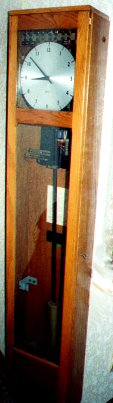
Larger exchanges used master clocks to produce timing pulses. Depicted
here are, on the left, the Clock 36,
which produced pulses at 1, 6 and 30 second intervals. Note that no
face was ever normally installed in
the case of these clocks. I have fitted one here as this particular
clock is in my lounge! It also
drives all the other pulse clocks around my house and museum. On the
right is the smaller Clock 46,
which produced fewer pulses for use with manual switchboards.
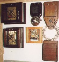
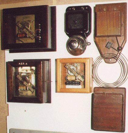
This is a selection of "clocks" driven from the master clock, which
produced further pulses at
longer intervals, and also some exchange alarm bells. The box at bottom
right is an old howler device,
used for making a loud noise on a subscribers line, should he be so
careless as to leave his receiver
off the hook!
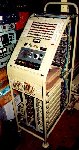
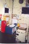
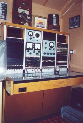
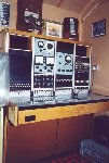 Associated
with all exchanges are testers built especially for testing
a specific function. On the left
is a Tester 219A, a trolley mounted device for plugging in to the
exchange racks containing
the Coin & Fee Checking relay sets used to operate pay on answer
coin collecting boxes. This tester
was in fact a full routiner, which would automatically step on to each
relay set in turn and sequentially
test each function for correct working. Faults were printed out on the
exchange fault recorder. The tester
is fully Strowger in construction, using only standard relays and
uniselectors. On the right is a Test Desk.
Each main exchange would have one or more of these test positions so
that engineers could test lines
to diagnose faults which had been reported either by subscribers or by
the automatic routine testing.
Associated
with all exchanges are testers built especially for testing
a specific function. On the left
is a Tester 219A, a trolley mounted device for plugging in to the
exchange racks containing
the Coin & Fee Checking relay sets used to operate pay on answer
coin collecting boxes. This tester
was in fact a full routiner, which would automatically step on to each
relay set in turn and sequentially
test each function for correct working. Faults were printed out on the
exchange fault recorder. The tester
is fully Strowger in construction, using only standard relays and
uniselectors. On the right is a Test Desk.
Each main exchange would have one or more of these test positions so
that engineers could test lines
to diagnose faults which had been reported either by subscribers or by
the automatic routine testing.
Click on either photo for an enlarged view, using your browser's
Back button to return.
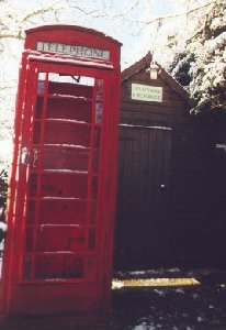
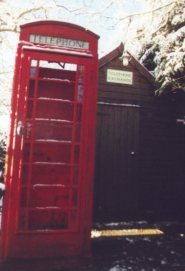
And as we come to the end of the first part of our tour, here is my
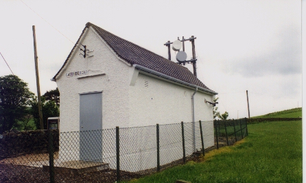
Kiosk, in the snow. This is the famous K6 which
used to stand in Jerico in Oxford. The building behind is my UAX13
building. Although it's no A or B
type building, the position is quite typical of many kiosks outside
small rural exchanges. I have started
the long process of restoration. After further removal of loose paint I
am ready to start replacing all
the glass panels, most of which I have now removed and cleaned out
ready for replacement. Many of the
existing panels were of the modern acrylic type which went opaque in a
very short time. Hopefully I might
be able to finish this project, given some decent summer weather!
Postscript. The restoration was finished in 2000. I would add a recent
photo but I have to say that after another ten years of the British
weather it needs repainting yet again! It does now house a payphone 700
working via the coin and fee relay sets in the MNDX.
Here we pause in the tour. If you would like to see some more
interesting telephone equipment, including
some of the small PAX equipment in the collection,
please click here
To return to the home page, click here
This page is maintained by Martin


 Associated
with all exchanges are testers built especially for testing
a specific function. On the left
is a Tester 219A, a trolley mounted device for plugging in to the
exchange racks containing
the Coin & Fee Checking relay sets used to operate pay on answer
coin collecting boxes. This tester
was in fact a full routiner, which would automatically step on to each
relay set in turn and sequentially
test each function for correct working. Faults were printed out on the
exchange fault recorder. The tester
is fully Strowger in construction, using only standard relays and
uniselectors. On the right is a Test Desk.
Each main exchange would have one or more of these test positions so
that engineers could test lines
to diagnose faults which had been reported either by subscribers or by
the automatic routine testing.
Associated
with all exchanges are testers built especially for testing
a specific function. On the left
is a Tester 219A, a trolley mounted device for plugging in to the
exchange racks containing
the Coin & Fee Checking relay sets used to operate pay on answer
coin collecting boxes. This tester
was in fact a full routiner, which would automatically step on to each
relay set in turn and sequentially
test each function for correct working. Faults were printed out on the
exchange fault recorder. The tester
is fully Strowger in construction, using only standard relays and
uniselectors. On the right is a Test Desk.
Each main exchange would have one or more of these test positions so
that engineers could test lines
to diagnose faults which had been reported either by subscribers or by
the automatic routine testing.