From the Engineers point of view.
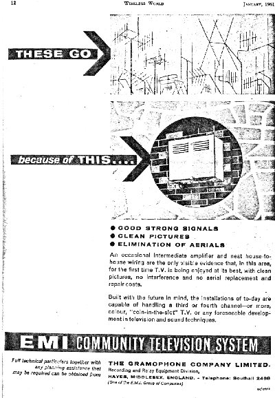
The EMI Wideband Community Television System
Having examined the Abingdon company as far as records allow, we can now look at the hardware and technical aspects of the system. To some this will be too technical for general reading, but for those with an appreciation of the problems which may be apparent, this could be the most interesting part.
The system adopted for Abingdon was entirely designed and produced by EMI, as a suite of component parts which were accurately matched to one another, from the 'head end' to the consumers TV aerial plug, rather like in any one manufacturers central heating systems; although all systems are designed individually for each type of house, they are all made up of the same component parts chosen from a catalogue. The cable itself was not manufactured by EMI of course, but was of a specification to match the designed system. The Abingdon installation was not unique in any way, and similar examples are to be found elsewhere, but this story is not complete without full details of the equipment that 'did the work'.
The Head End
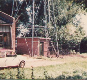
The head end, or aerial station, was obviously the backbone of the system, and no expense was really spared here. The 165 ft hot dipped galvanised tower, of lattice construction, was built a few yards to the north of the mill stream, on land previously used, and probably reclaimed, as a rubbish tip. Though occupied by William Press and their buildings, this part of the site was still to be developed, and the vehicular access to the tower was, at that time, a rough track. Now building has encroached right to the foot of the tower, virtually into the compound itself, and good roads exist for access to various let premises. The tower is around 15 feet square at the foot, and tapers to 2ft square at the top, and is entirely self supporting. It was built on a concrete raft, and all four legs electrically grounded into a buried wire mesh. There was an access ladder running the whole length, and the compound of 30 feet square, was fenced with a 6 foot fence topped with barbed wire.
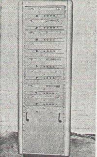
Inside the base area of the tower was sited the hut(fig 12) for the amplifier equipment from which the trunk cable runs. The 72 square feet of space was adequate to hold the rack of equipment(fig 13) and bench space for service work. Electricity was supplied by underground cable.
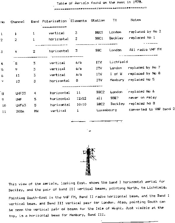
Contractors installed the heavy duty aerials required at the top, for the initial service, and ran feeders to the hut. The aerials used were of a very high durability, manufactured by Commercial marine Ltd (G&SD?) of Rochester. They were mounted using large 2in diameter scaffold type poles, with heavy duty clamps, and would have probably been safe for 50 years!(fig 14)
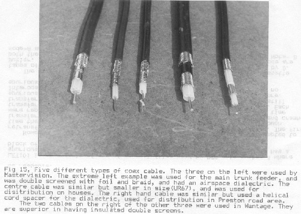
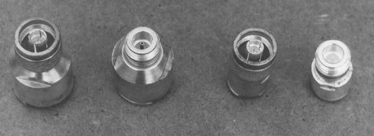
The aerial feeders used were, two sizes of coax for TV and VHF radio, and a twin balanced screened feeder for the medium wave aerial. This meant a total of six assorted feeders. The BBC1 aerials and the VHF radio aerial used the thinner coaxial cable (UR57), and the ITV band 3 aerials used the same coaxial cable as used for the trunk feeder throughout the town(fig 15). This was a large diameter(5/8") cable of very low loss. All coax cables were 75 ohm, air-spaced and double screened with braid covered by foil. This type of double screened cable was particularly chosen for the system as a whole, due to it's immunity to interference both into and out of the cable, hence the term 'protected cable'. Most cable terminations throughout were 'N' type connectors, with silver plating protection(fig 15a). Table 1 gives a list of aerials in detail. Some of the aerials later fitted are thought to have been experimental only, and were never used for relay. The UHF array for London was used retrospectively in place of the southern band 3 ITV aerial, and used that feeder. A masthead amplifier was used for this too, mounted in a spare distribution amplifier box, at the tower head. This was believed to have been a valve unit at first, later changed to a transistor unit(fig 16).
The UHF 625 line signal for BBC2 was converted into a VHF 625 line signal on channel 11, by demodulation and re-modulation at the required frequency, with the appropriate video and sound standards for VHF. The converter units were mounted on the wall of the hut in spare ALC amplifier boxes.
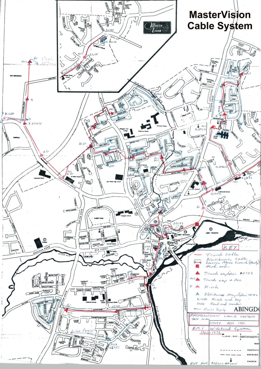
In the hut at the tower base, a 6ft rack of equipment was installed(fig 13), including channel pre-amplifiers, power supplies, combiners and associated equipment. Each aerial feeder would terminate in a channel pre-amplifier, and these signals once amplified, would be fed into a combining device, directly or via a channel converter when desirable, so that all signals were available on the one cable, with the correct levels set up with respect to each other, avoiding cross modulation which could otherwise occur. The output was split and amplified into two trunk cables, which underground ran in two directions(fig 17), away from the tower. The first ran north-east, under the railway, to Barton lane, where the first trunk amplifier was sited. For an example plan of a typical system, click here.
The Main Trunk Feeders
All trunk cabling was buried in specially dug trenches and rumour has it that service was often being interrupted due to road works cutting the cable. When this happened, the large contracting firms involved would only be concerned with paying the cost from insurance money, and did not respond easily to the urgency of the need to repair, caused by hundreds of homes with no TV signals.
Trunk Repeater Amplifiers
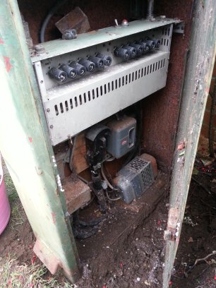
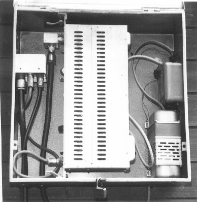
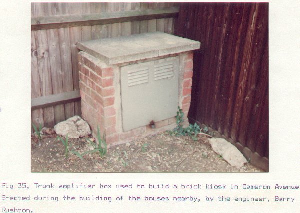
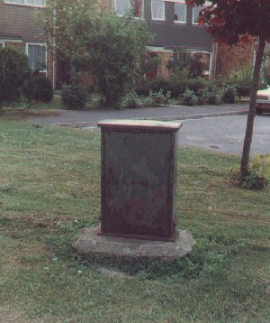
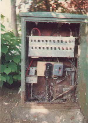
A trunk amplifier was designed to be mounted in a special rain proof wall box(RE 780) about 20"x20"x7" painted greenish grey(figs 18, 2, 35, 38a, 38b). The trunk cable would come up above ground, to an amplifier, usually through a conduit pipe against a wall(fig 19), and would sometimes continue along a row of houses where possible, or otherwise would go back underground, as local geography permitted. Where an amplifier was needed away from any suitable walls, a roadside kiosk would be used to house the amplifier(fig 20). The Barton lane amplifier was such a kiosk. These cabinets were green, about 4 feet high by 2 feet wide, and 9 inches deep, all with separate keys.
In most of these kiosks a separate electricity board supply had to be provided with switch-fuse etc. An exception was in Cholswell road area where no mains supply ran, and so wires were laid with the coax cable, from adjacent kiosks. No meter was needed as a constant 24 hr supply is charged at a fixed rate. The consumption of a typical trunk amplifier would be about 50 watts.
The trunk cable entered the actual amplifier via an equaliser unit. This was a small box, about 2 inches square, with N plugs attached. It was effectively a high pass slope filter(figs 20b,20c). This was needed because the high frequencies of band 3 would be attenuated in the cable much more than those of band 1, and it was necessary to therefore attenuate band 1, to provide a signal of equal level across the spectrum, to feed into the flat response amplifier. Each amplifier had a manual gain setting, except that agc could be selected for use in ALC amplifier units. It was usual to adjust the gain to be as high as possible without causing cross modulation, and this level would typically be around 40 db. To maintain this reasonably constant at the amplifier, a constant voltage transformer(fig 18) was often used in the supply.
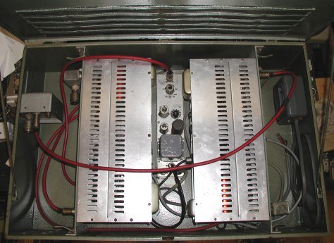
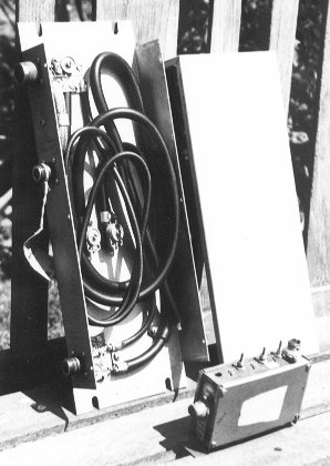
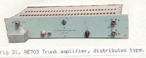
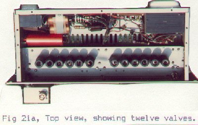
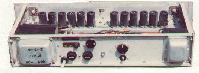
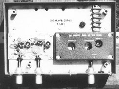
The amplifier itself was an RE703 19inch rack mounting unit, about 4" high and 7" deep(fig 21 and fig21a). The wall boxes were designed to take such a mounting on a slide in rack(fig 18), but in the kiosks a simple Dexion bracket was furnished(fig 20a). On the front panel are the input and output N connectors, and the gain control. Each input or output has a separate N connector with attenuator, to enable monitoring of input or output signals. At the rear, besides the usual mains tapping adjustments, was the ALC/manual switch which permitted the gain to be controlled either from the front panel control, or by an externally supplied bias, via a 2 pin plug(fig 21b).
The design of the amplifier was such that individual valve failure was not a disaster, and would only cause a slight loss of signal. This was because the 12 EF95 valves were wired effectively as 2 stages, each with six in parallel, and a delay line system was used to distribute the signal across the 6 in each case. This is why they are termed Distributed amplifiers(fig 21c).
Emividers
The output signal from the amplifier would then either pass into the next run of trunk cable, or if more than one trunk or if spur cable is to be supplied, would pass into a cable dividing network, called an Emivider(RE729/731, (circuit), figs 18, 20a, 36). These 2,3 or 4 way splitters were built into small metal boxes about 5"x4"x4", with an inset bottom panel, on which the N connectors were mounted. This design meant that up to a point, they were waterproof and could be sited in the open, should a split be needed in the trunk cable away from an amplifier. More usually, the split was for one or more spur cables of distribution to leave the amplifier, to be routed along houses, and the trunk would continue from another outlet on the splitter. Unused outlets on the splitter would be terminated with N plugs containing 75 ohm resistors.
Trunk Repeater Amplifiers with Automatic Level Control.
Trunk repeater amplifiers would generally be sited at about 200 yard intervals, or less in certain circumstances, and every fourth repeater would include an automatic level control. This was needed because of the variation in signal level caused by cable temperature changes, which would be significant after about half a mile of cable.
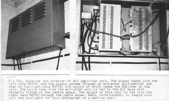
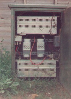
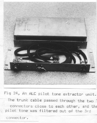
The ALC repeater consisted basically of 2 RE703 amplifiers with additional circuitry for the automatic control. Intended to be mounted in a larger wall box, about 31"x20"x7"(fig 22, fig22a), they were also just about fitted into kiosks when necessary(fig 23). The trunk signal was amplified by the first RE703, and then passed to the second, via a pilot tone take-off unit(RE744b), which consisted of cable stub devices(fig 24).
The pilot tone was a carrier inserted at the head end, out of band at 174.25 Mc/s, using device RE768. This signal when extracted by the RE744b, would be fed into a detector unit which produced a corresponding negative bias voltage, applied to the the AGC input of the second RE703. Variations in cable signal and therefore in the level of the pilot tone, would cause the gain of the second RE703 to be adjusted accordingly(fig 25)
The Distribution Cables.
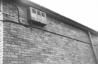
Distribution cables to houses normally ran from the Emivider on the output of a trunk repeater. Since the distance which could be covered from one of these amplifiers was limited, the trunk cable must run through a distribution area. An area would be an estate of houses or a group of streets. The cable used from this point would be 3/8" diameter air-spaced UR57, double screened coaxial cable. It would often be routed along the eaves of houses, crossing gaps between on a catenary wire. Road crossings, as with the trunk cable, were usually underground. In terraced property, and on blocks of flats(fig 26), the cable could be routed along a wall by some natural line of the masonry, or even inside the roof space of flats. In the more recent housing developments, eg Dunmore farm estate, the cable was routed underground between houses during construction, and also run in wall cavities. Some of these more recent properties also used a heliax type of cable where the inner conductor dielectric was a spiral cord air-spacing, rather than a honeycomb(fig 15).
On the Fitzharry's estate, wayleave was granted with the provision that the cables were not to be strung across gaps, but to be routed down and around the top of intervening garage roofs, or alternatively underground. In any coaxial distribution system the extra cable which one must allow for, beyond that indicated on a plan map, is 25% extra, to allow for variations in height etc, and other deviations. The Fitzharry's stipulations must have made costs of cable and labour even more expensive.
Generally cables are routed at the rear of buildings where possible, in order to hide their presence, particularly where an amplifier was to be mounted. However, this may not always be done when the habits of some areas meant that most TV sets were at the front of the house. This was the case on Fitzharry's estate, and so cable was routed along the front eaves. Since an amplifier would have to be sited at the back, this meant even more cable complications, except that in some cases mounting the box on the side of a garage wall would help.
Emisplits.
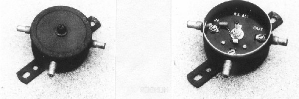
At intervals on the distribution spur cables, the route would have to be divided, as with trunk cables, and this was often achieved with Emisplits(RE851,fig 27), small round boxes about 3" across. These were merely small cable equivalents of the trunk Emividers, but normally only for two way splits.
Extension Amplifiers.
After 10 homes or so of distribution it would be necessary to amplify the signal with a small distribution, or extension, amplifier(RE702a,(circuit), fig 28). These were usually in smaller wall boxes of around half the size of those used for trunk repeaters(fig 29), but they were also sometimes mounted in kiosks. They used 10 6CY5 valves and were similar in principle to RE703 amplifiers, only of higher gain.
Not more than 2 of these should be cascaded one after the other, in any run of spur cable. It is however possible to effectively feed more cable by splitting several times, than by using one long run, and the distance that can be served from any one amplifier depends on how many splits and taps are attached to the cable. Each time the cable is split, a 3db loss will occur(fig 30). Mains supplies to amplifiers mounted on house walls were liable to be taken off either before or after the meter, according to householders co-operation or SEB requirements. If taken after the meter then the occupier would be compensated for the power used. If connected before the meter then a separate switch-fuse may be used.
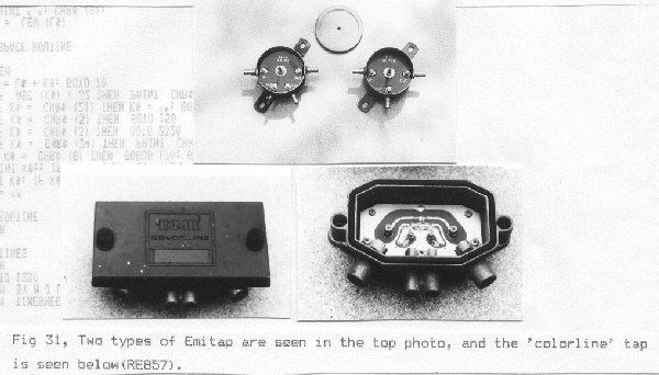
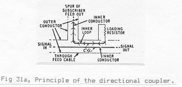
Emitaps.
At each house the subscribers tap off is sited, or sometimes one to a pair of houses. This is mounted in the run of cable under the eaves or wherever appropriate. This was either a small round box with one or two outlets(directional coupler), similar in appearance to an Emisplit,(RE 720), or a rectangular box with a plastic top, with two outlets(RE857,fig 31), which was part of the EMI Colorline system. Also Colorline Emisplits were similar in appearance. The round Emitap was the famous EMI directional coupler, constructed from a length of cable with a tap-off wire inserted to extract the signal, but designed not to allow back insertion of interference(fig 31a). This is similar to wave guide practice. The attenuation level of each of these taps was chosen according to the level of the signal at that point, caused by the progressive drop in signal level along the spur away from the amplifier. Three levels of attenuation were available, the highest being used next to the amplifier, and a typical value would be around 22db loss needed to reduce the level to that suitable for a TV set.
The End of the Line.
Subscribers down leads ran from the Emitaps to a white outlet box in the home where the signal was matched into two Belling-Lee TV sockets, one for TV and one for FM radio(fig 32). In more recent developments the Emitaps were mounted just above the ground level at the front of houses and cables run in the wall cavities to subscribers outlets, and Emitaps were sometimes mounted inside the cavity behind a plate.
Changing Technology.
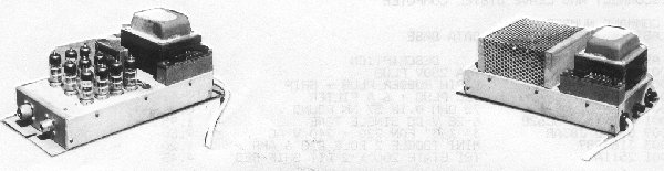
On the Tithe barn estate, one of the most recently built and wired, transistor amplifiers of various makes were now available which required much less maintenance(no valve changing), and less power, and were smaller in size. The EMI Colorline system amplifiers were available when the Preston Road area was wired,(fig 33), and were probably some of the few items recovered on liquidation, being of recent technology at that time.
Modern wideband equipment for TV distribution is capable of covering Band I to Band V, entirely transistorised, line powered with low voltage, and incorporates integral attenuation and/or equalising networks, all in a much smaller and neater box. Also, in the example in fig 34,the signal is split at entry and then fed into two separate amplifiers, a much more efficient way, but this would be a most cumbersome idea if tried using the old EMI valve units!
To see a schedule and some corporate pictures of the EMI equipment used in the system please click here.
The future, or 'revitalising' of cable TV.
At the time of writing discussion has taken place at parliamentary level on the re-introduction of, or improvement of, existing relay operations, on a national scale. This has been sparked off largely by the emergence of satellite TV reception, where individual aerial systems would be very expensive. Also, modern systems could carry data transmissions including two way data transfer, enabling access to computers and database facilities from the home, rather than attempting to use an overloaded telephone service.
The advantages/disadvantages and economic soundness of such proposals are debatable, but in their day systems such as the Abingdon EMI installation proved that such services had promises.
However, it seems to the author that since man has invented radio, and no longer needs to rely on expensive cables for broadcasting, and considering the environmental upheaval of installing and maintaining such a national system, that the cost of such a system would now be non-viable and too expensive for the majority to wish to subscribe to.
It also seems that cable TV as Abingdon knew it, is now very much a thing of the past, but it was a quality service to the borough which should be remembered with reverence, resting but not forgotten.
Post-script
Since the bulk of this pamphlet was written one large change has taken place which cannot remain unmentioned. This 'grevious act of vandalism' is vested in the form of the removal of the Head-End mast from the Abbey meadows. In the autumn of 1982 it made way for the building of industrial units as part of the development of the site instigated by Burgess & Sons Ltd. Although this, the most important relic of the company has gone, I am sure that the volume of cable and equipment still spread so diversely around the town, will remain in parts for a long time to come, enabling readers to still see something of the network in person.
MJL April 1983